Most modern engines use coil-on-plug distributorless ignition systems managed by an engine control module (ECM). However, many vehicles built before the mid-2000s use distributors.
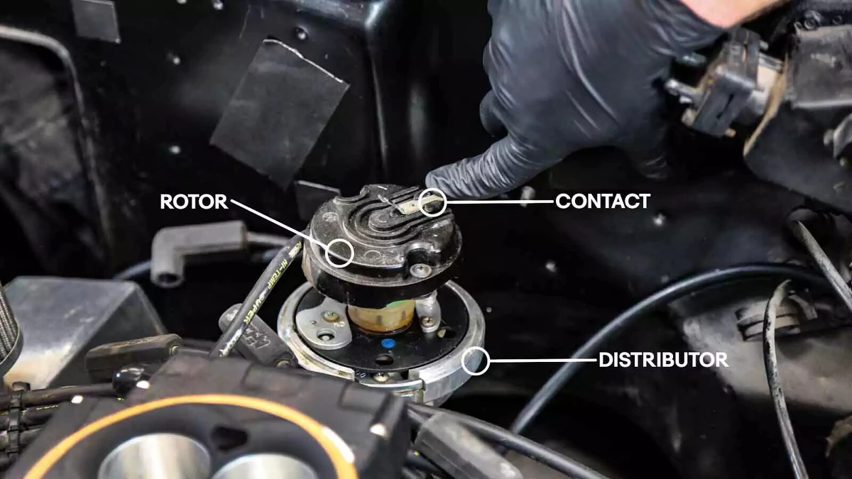
A distributor does exactly what its name implies. It distributes the power from a single ignition coil to each spark plug (via a spark plug wire) in a sequence based on the engine’s firing order. Most engines use a gear on the camshaft to drive the distributor, which spins a rotor inside the unit. As the rotor spins, a steel spring contactor glides under the contact for each plug wire. The electricity—which arcs to the plug contact—goes to the spark plug, which ignites the fuel.
While distributors can last for decades, they are electro-mechanical devices that eventually wear out. A failing distributor can misfire, not make contact, or seize up, causing engine damage.
Multiple problems can affect the distributor or the inner electronics. If your vehicle stalls, misfires, is hard to start, or won’t start—or the check engine light illuminates with an ignition code—investigate the ignition system and distributor for issues.
Tips and Tricks
- There are three types of distributors: mechanical point, electronic, and engine control module (ECM).
- Most vehicles built before the early 1970s used ignition points rather than an electronic trigger.
- From the early 1970s through the mid-1990s, vehicles used electronic distributors.
- Distributors using ECMs, which emerged in the early 1980s, took over by the early ’90s. The main difference between an electronic and ECM-controlled distributor is whether the engine is carbureted or has electronic fuel injection (EFI). Engines with EFI typically use ECM-controlled units.
- From a mechanical perspective, this project is not difficult. However, it can be challenging to establish the correct timing and firing. If you do not have the timing or firing order right, the engine will not run well, if at all. This is an advanced project that involves precise tuning.

The most accurate way to install a new distributor is to set the engine to top dead center (TDC) on cylinder 1. This process continues through multiple steps of this guide.
Top dead center is the position of a piston at the top of the cylinder, closest to the cylinder head.. There are two positions of TDC for every cylinder—one for the compression stroke and the other for the exhaust stroke. The engine must be at TDC for the compression stroke, when the spark plugs fire.
To find TDC, first, locate cylinder 1, which is the cylinder closest to the timing belt or chain for inline engines, and the forward-most cylinder for V-type engines. On a V-engine, one cylinder head sits slightly in front of the other. Cylinder 1 is the closest to the timing belt or chain on that bank. Confirm these locations in your vehicle’s repair manual.
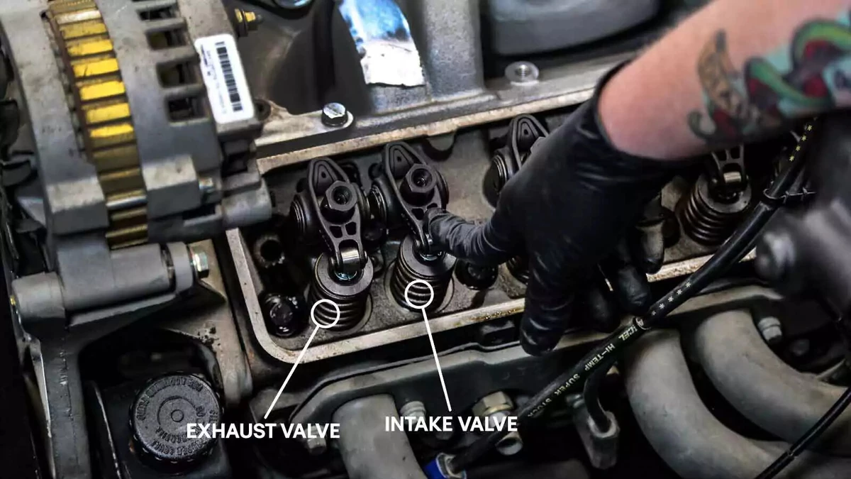
Locate the intake valve, which is next to the exhaust valve for the first cylinder. The exhaust valve lines up with the exhaust manifold port. The one next to it is the intake valve.
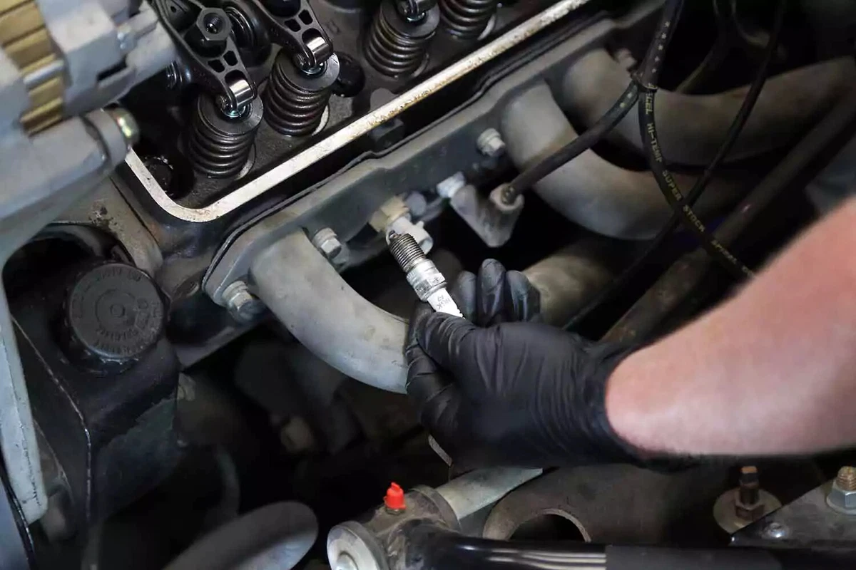
Remove the spark plug from cylinder 1 so you can access the combustion chamber.
This is a great time to replace the spark plugs and plug wires.
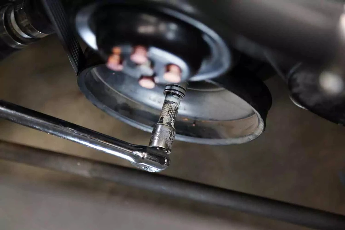
Apply a breaker bar with a socket to the crank bolt. Spin the engine to bring cylinder 1 to TDC. This might take some time to figure out. Watch the rocker arms to see when the intake valve closes.
When the intake valve starts to close, the cylinder is approaching TDC. Here’s another clue: The rocker arm will move up to a resting position and be very slightly loose at TDC—by a tiny fraction of an inch.
The intake valve should close immediately before TDC on the compression stroke. If the exhaust valve rocker arm is moving, you are on the wrong stroke. Spin the engine 360 degrees to reach the compression stroke.
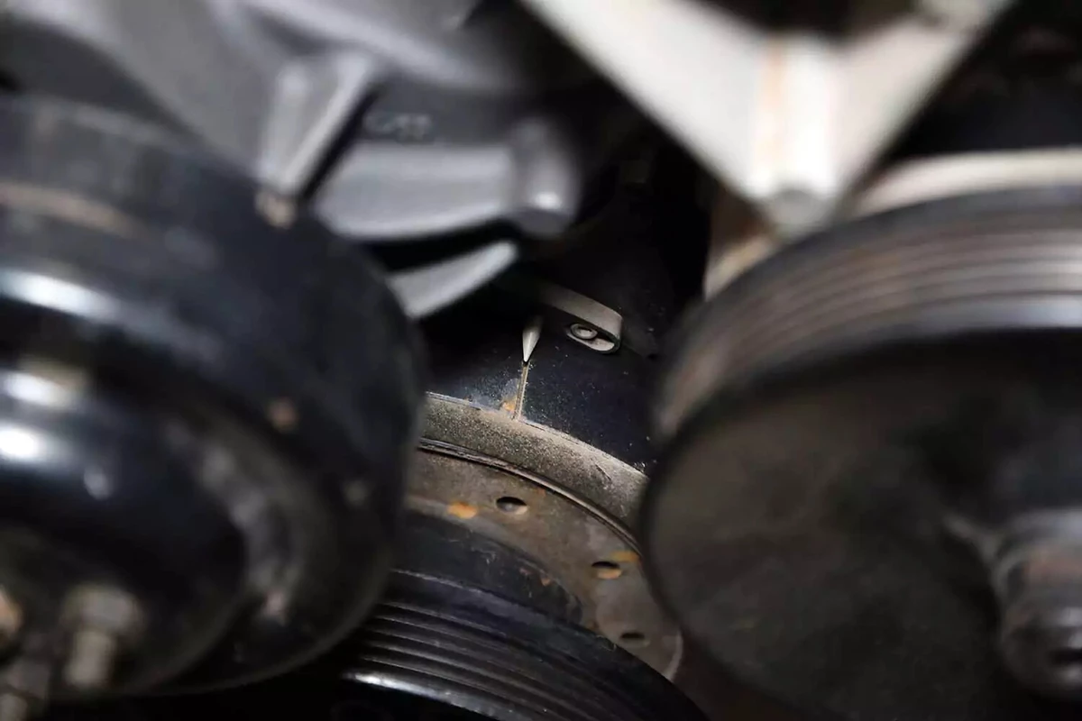
The engine should have a timing point or tab that lines up with a mark on the crank pulley/balancer when you are at TDC on cylinder 1. (See the photo for this job’s Step 24.)
If the mark doesn’t line up, verify you are on cylinder 1. That’s the one that is at the absolute front of the engine—right behind the crank pulley/balancer.
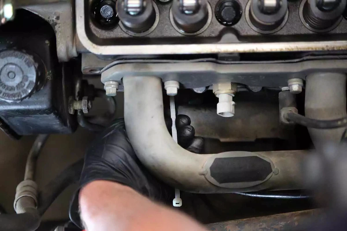
Use a zip tie or thin screwdriver to probe the cylinder for the top of the piston. Don’t push in too far if using a metal object.
With one hand on the breaker bar, rotate the crankshaft back and forth to feel the movement of the piston with the zip tie. Once you feel the piston rise, continue rotating the engine until it stops briefly then begins to travel back down. Rotate the engine back to TDC until the piston stops. This is TDC for cylinder 1. You shouldn’t need to move the crank more than a few degrees in either direction to find TDC.
Do not spin the engine again until this job is complete. Wait to reinstall the valve cover in case you need to reset the engine to TDC.
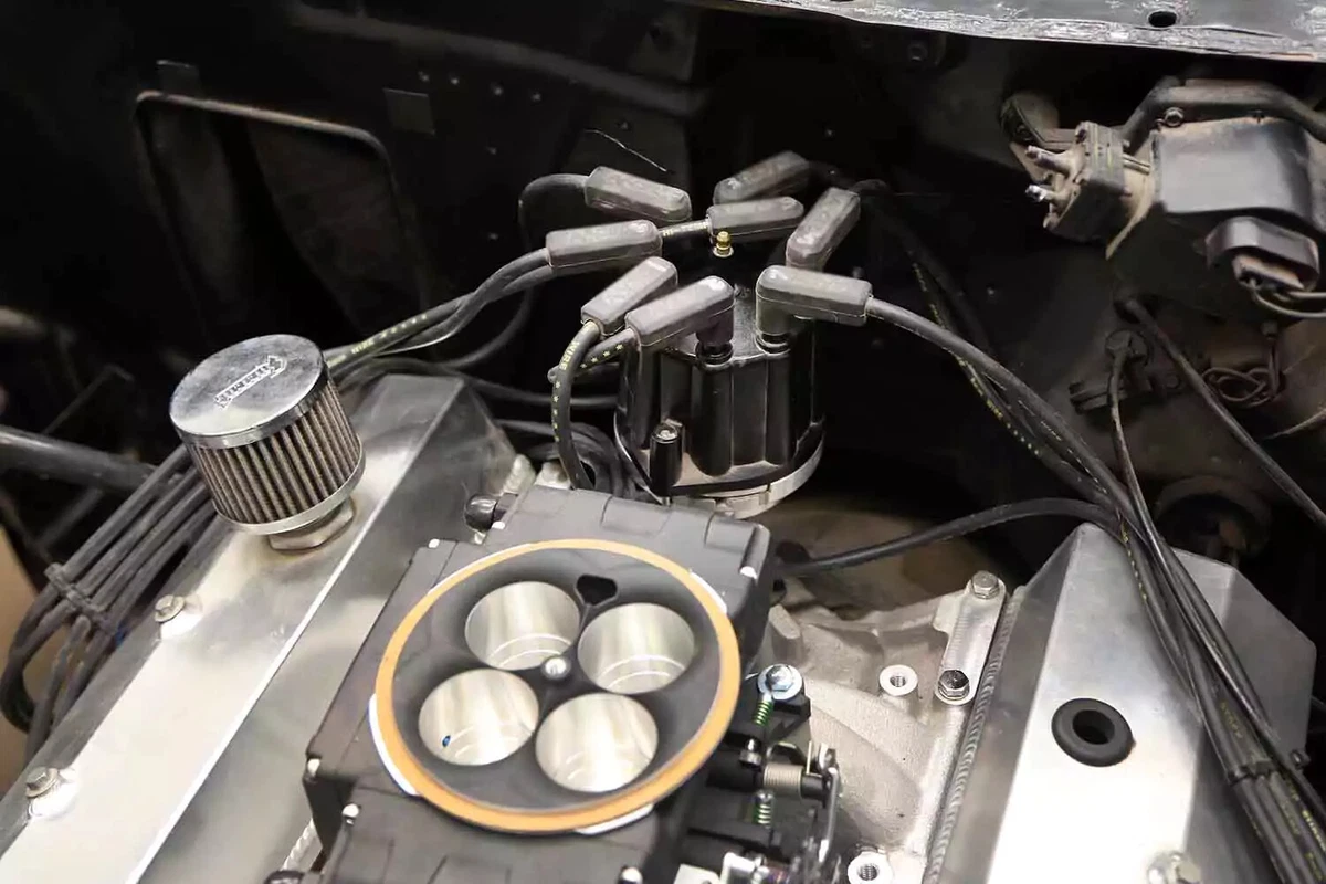
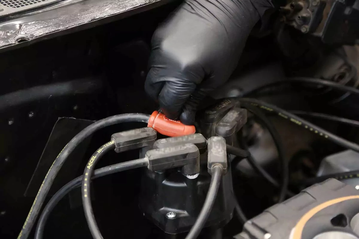
Ensure the engine is set to TDC for cylinder 1. Now, locate the distributor, which could be at the front, rear, or side of the engine.
The cap will have plug wires attached in the correct firing order. It is a good idea to mark each wire with the position of the spark plug (not the order of the cap position). This engine’s firing order is 1-8-4-3-6-5-7-2, but this changes based on the engine make and year. It’s important to get the precise order correct.
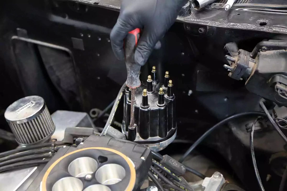
Remove the plug wires and cap. If your cap is in good shape, keep the wire connected to it. This can be helpful for some installations, particularly ECM-controlled units. (More on that later.)
Older vehicles use vacuum advance, which relies on a small vacuum line from the carburetor or throttle body to control the timing advance. If your vehicle uses a vacuum advance, remove it.
Two screws or spring clamps retain the cap. Remove them.
At this point, the process splits into one of these two methods: from scratch, as we are showing, and by position.
Regarding the “from scratch” method, it’s possible to remove the old distributor and install the new one without setting TDC or timing the engine. It requires skill and experience, so we will show you the full process.
The second, “simpler” method requires extra care when removing the distributor.
- The plug wires cannot be moved on the cap.
- The rotor must stay in exactly the same position in relation to the cap.
- The body of the distributor must remain in the same position in relation to the rotor.
This works better for pulling and reinstalling the same distributor but is more difficult when installing a new distributor. If you are new to this, we recommend that you learn how to find TDC and set the timing. If you make one minor mistake using the simpler method, you’ll need to start over.
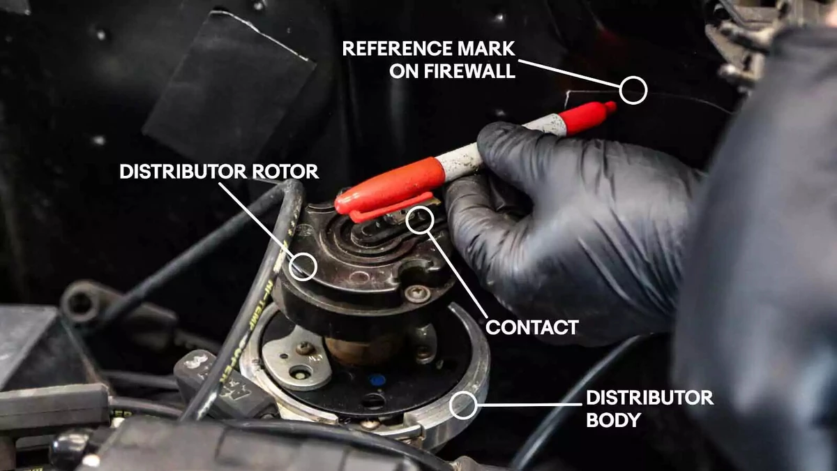
If you use the simpler method or are reusing the cap wiring positions, mark the position of the rotor contact on the vehicle body or engine.
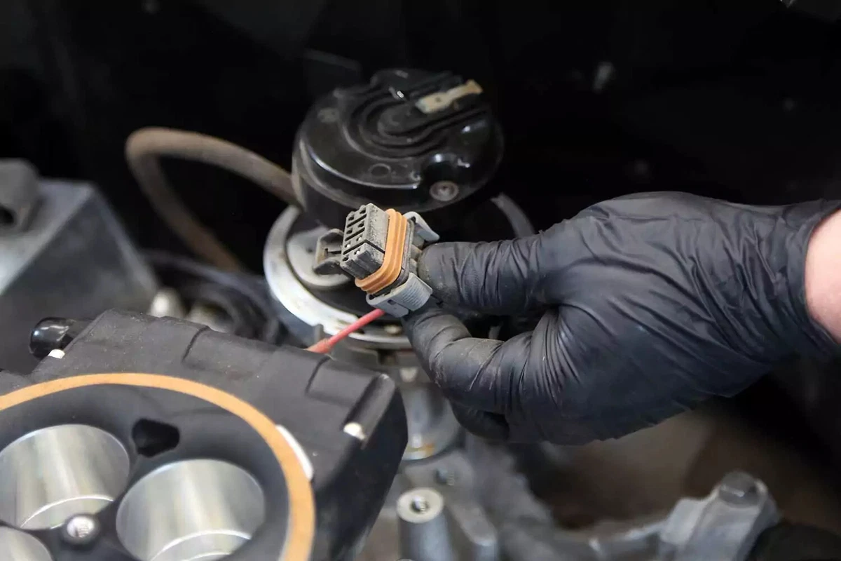
An electronic distributor has a large wiring plug or individual wire pins. Disconnect them now. If your vehicle has individual wires, note their positions on the distributor.
A points distributor has two wires coming out of the bottom and leading to the ignition coil. Note their positions before removing them.
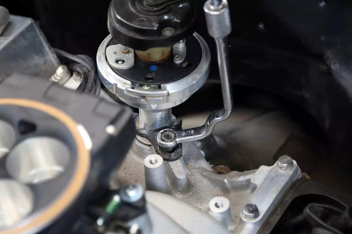
Use a distributor wrench or stubby wrench to remove the lockdown bolt from the distributor’s hold-down bracket.

Lift to remove the distributor from the engine. Because the gear teeth are set on an angle, the rotor will spin slightly in relation to the body as the gear disengages from the cam gear. Note the direction and degree of how much it moves.
You’ll need to replicate that motion in reverse as the distributor goes back during installation. This will be important when you are trying to replicate the original rotor position.
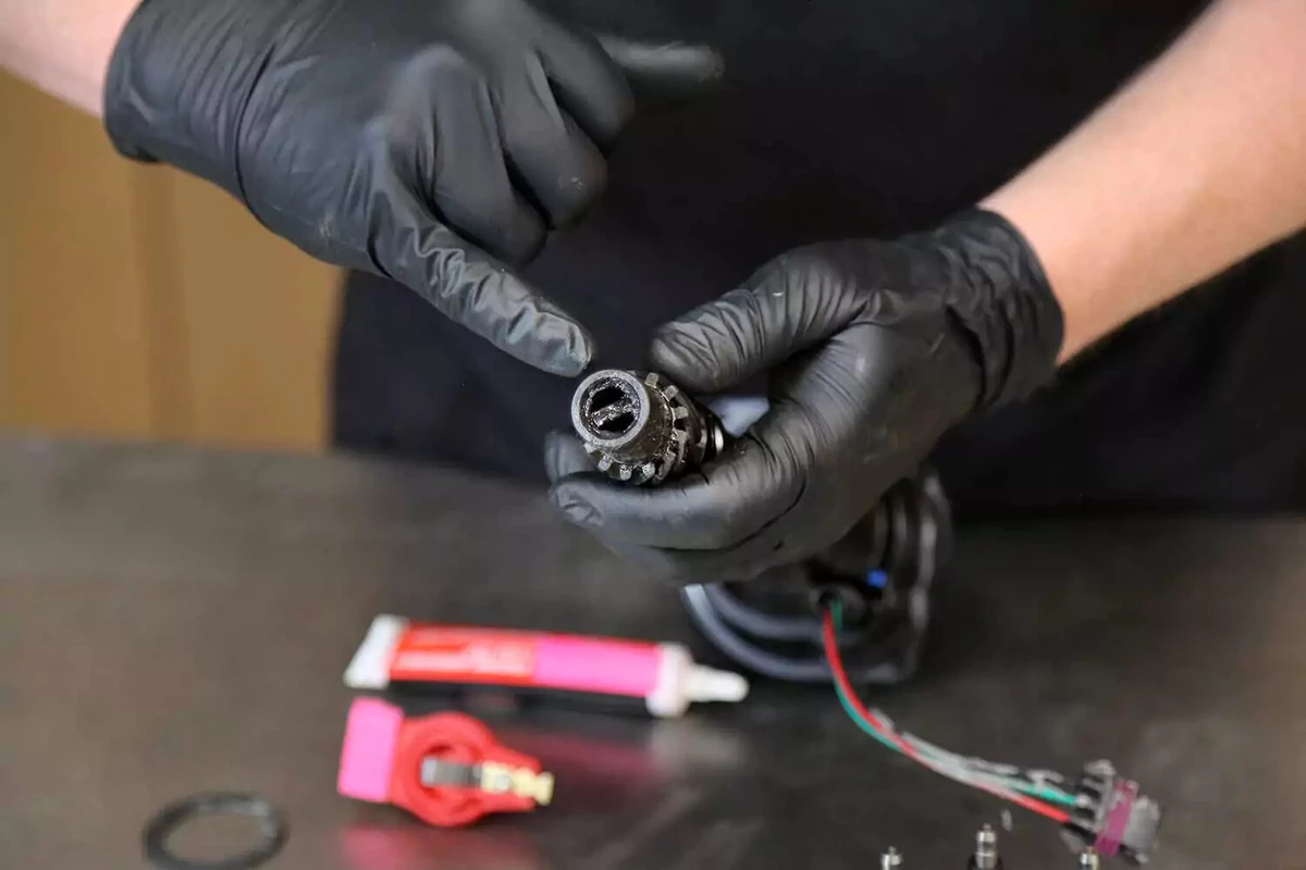
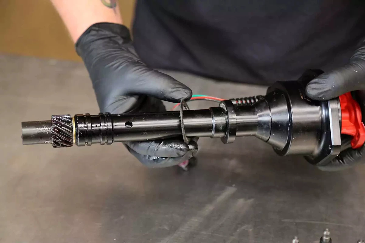
The gears on the bottom end of the distributor mesh with gears on the crankshaft, ensuring the distributor shaft rotates in sync with the crank. Some engines drive the distributor directly from the camshaft instead.
For many engines, the bottom of the distributor shaft drives the oil pump. How the distributor engages the oil pump driveshaft varies. Many use a slot-and-tongue, although some use a hex shaft. Slot-and-tongue shafts are harder to engage on installation, as there are only two positions for the rotor to be in.
If the oil pump rotates, even a little, when removing the distributor, it will be difficult to re-engage it when reassembling components.
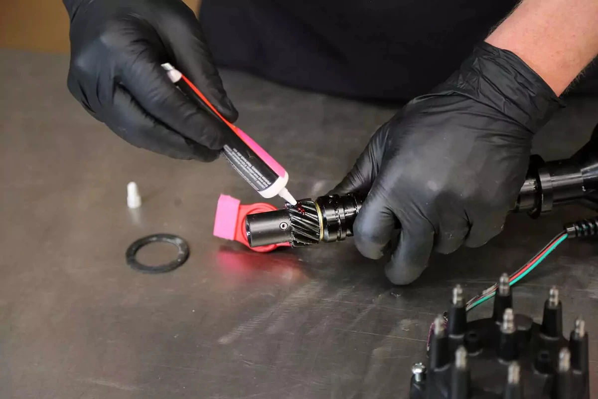
The drive gear requires assembly lube to ensure the gears don’t bind or seize on each other. Use dedicated engine assembly lube gel or paste, not wheel bearing grease.
Some high-performance engines and aftermarket camshafts require drive gears that are softer than stock gears. Verify that your drive gear is compatible with your engine’s camshaft. The correct drive gear could be bronze, iron, or steel.
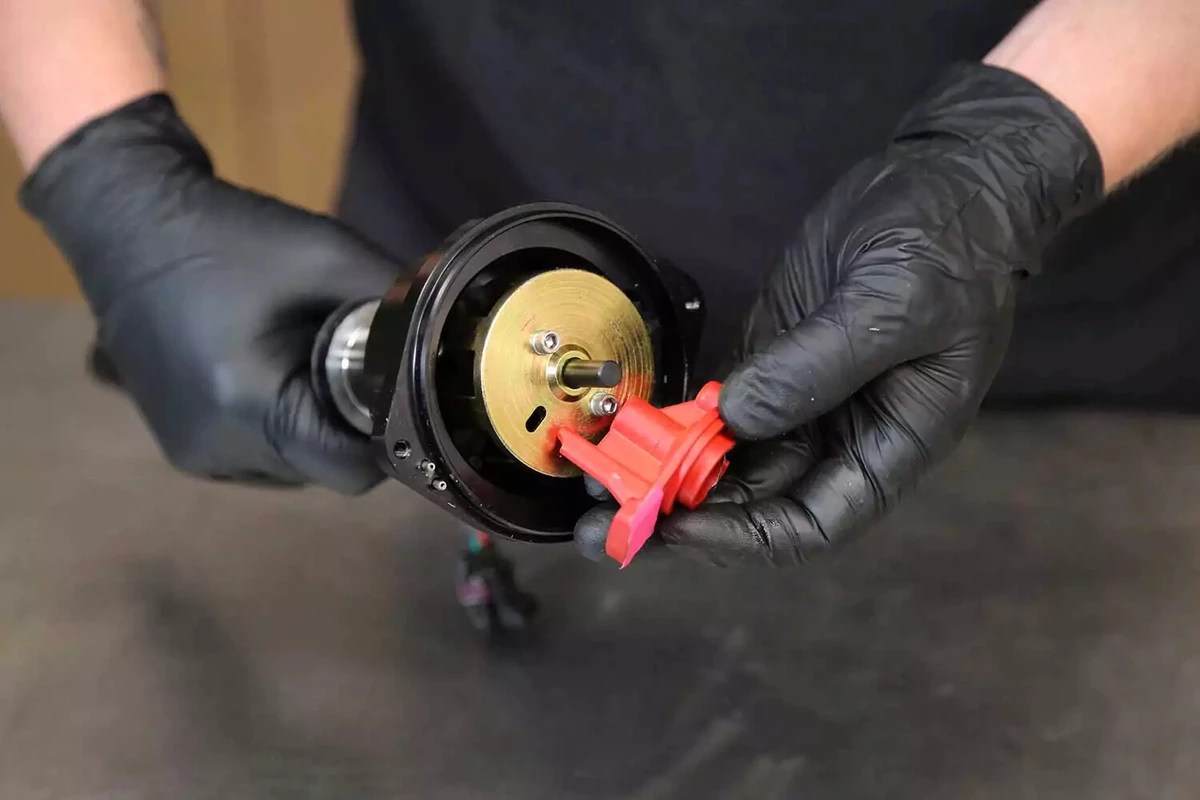
Install the new rotor to the distributor. Some slide on, while others bolt.
Slip the supplied gasket onto the base of the distributor. The gasket ensures there will be no oil leak.
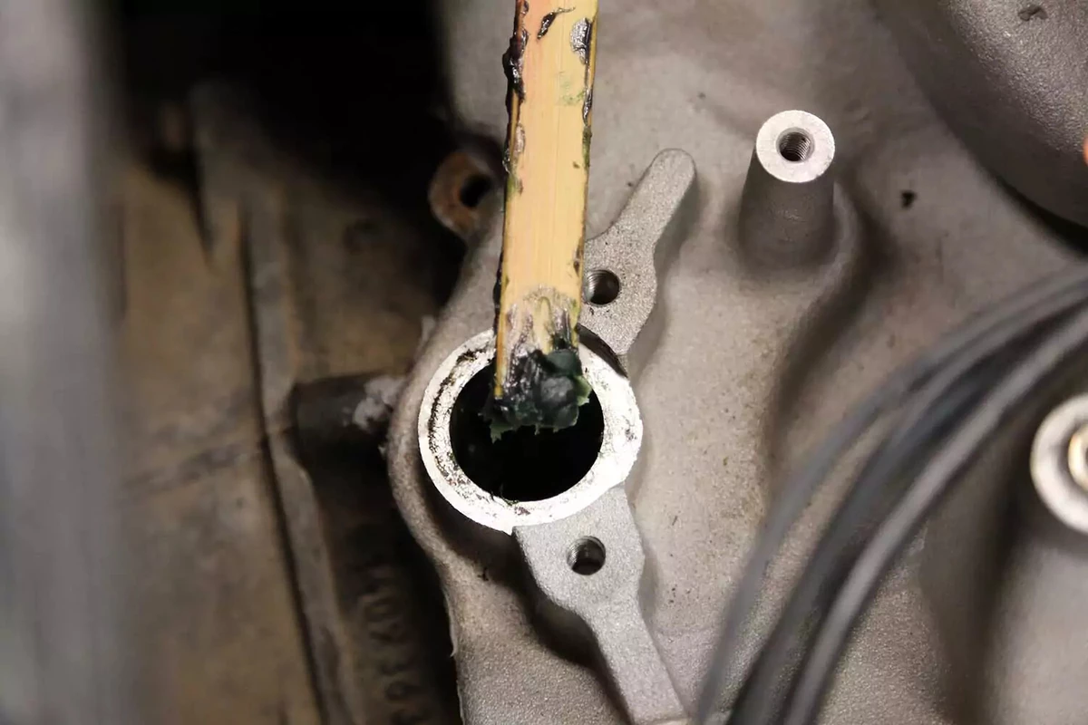
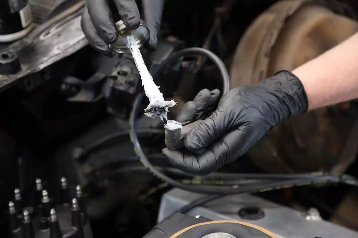
On some engines, the oil pump shaft might not stay centered in the bore, making it impossible to engage the distributor. Use engine-assembly paste to keep it in position. This task, requiring a long tool, can be tricky. We used a new paint stick to apply the paste to the shaft.
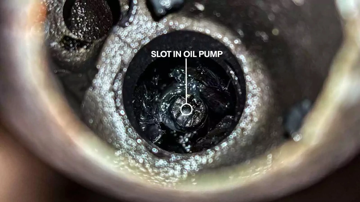
Look inside the engine to see how the shaft is centered in the hole and the direction of the slot for the tongue. Position the distributor shaft to match so the protruding tongue meshes as the distributor is pressed into place in its bore.
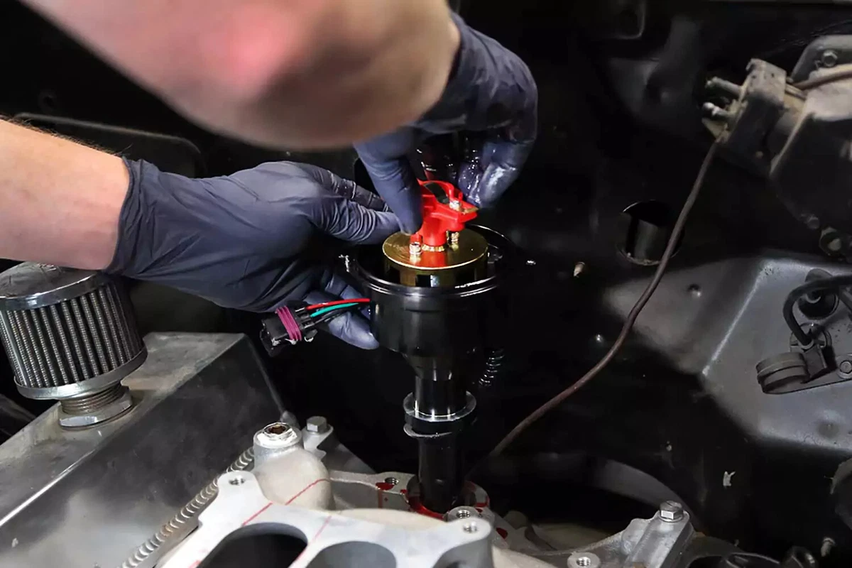
Hold the rotor in the desired position—slightly rotated, based on how it spun when it was removed. Lower the distributor into the engine, making sure it engages the oil pump drive shaft. It might take a few tries for it to seat with the rotor in the right position.
If using the simpler method, the rotor should point directly to the mark made earlier.
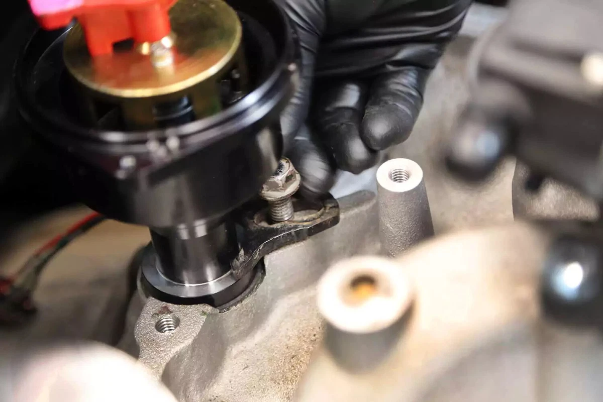
Reinstall the lockdown bolt and thread it snugly. Do not tighten it yet.
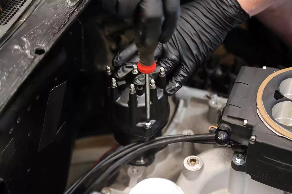
Adjust the distributor position so the rotor lines up with the cap on one plug terminal. This will be wire position 1. Install the new (or original) cap to the distributor.
If using the simpler method, the rotor should line up with the mark you made earlier for the distributor position.
Most ECM-controlled distributors require the distributor to be set to zero degrees TDC. If it is off by even a single degree, the ECM will not properly control the timing.
Some distributors have alignment lights, but most must be set with a timing light. Verify the required timing in your repair manual.
Apply a generous coating of dielectric grease to the plug wires. Attach them in the correct firing order, starting with wire 1.
Locate the next plug in the firing order, trace that wire up to the cap, and install it in the next position based on engine rotation. Check your repair manual to find out if your distributor spins clockwise or counterclockwise.
Attach the coil wire (if equipped) and reconnect the electrical connections in the same order they were removed. If your engine uses a vacuum advance, connect the vacuum line to the distributor.
Start your engine. It might not run great or start easily. But if you are close and the firing order is correct, the engine should start.
This step requires experience and patience. With the engine running, start adjusting its timing.
Find the correct ignition timing range in your repair manual. Connect your timing light to the battery and clamp the inductive clamp to the spark plug wire 1.
Locate the timing mark on the crankshaft pulley. There should be a mark, line, or pointer around the upper half of the crank pulley. The tab should line up with the mark.
If your engine has a vacuum advance, disconnect the vacuum hose. Plug the line from the engine to seal the vacuum leak.
Start the engine and let it idle. Carefully point the timing light at the crank pulley so you can see the timing mark and tab. The strobe light will flash every time the spark plug fires. The effect will visually stop the crank’s motion. Of course, in reality, it’s still spinning.
The timing light allows you to see the timing mark in relation to the tab. Most engines have a series of hash marks with zero degrees at the center—and 10 to 15 degrees advanced and retarded on either side. Each hash mark is one degree.
Carefully rotate the distributor body so the timing retards to the designated point described in your repair manual. Do not grab the cap or the wires. Hold low on the cap to avoid an electrical shock.
This engine requires 10 to 12 degrees of initial timing before TDC. This is advanced or before TDC, while the piston is still coming up inside the cylinder, compressing the air-fuel mixture. Retarded ignition timing means the spark is sent after the piston has begun to travel down.
Lock down the bolt on the distributor. Shut off the engine. Restart the engine. If it starts perfectly, you are done. If it backfires, misfires, is hard to start, or does not start, you went too far. Adjust the distributor to where it initially started and try again.
For ECM-controlled engines, the timing is typically 0 degrees TDC.
This is a basic guideline. Refer to your repair manual for details on setting the timing for your specific vehicle.
About the author

Share your feedback
This article is meant to provide general guidance only. Automotive maintenance, repair, upgrade, and installation may depend on vehicle-specifics such as make and model. Always consult your owner's manual, repair guide for specific information for your particular vehicle and consider a licensed auto-care professional's help as well, particularly for advance repairs.